
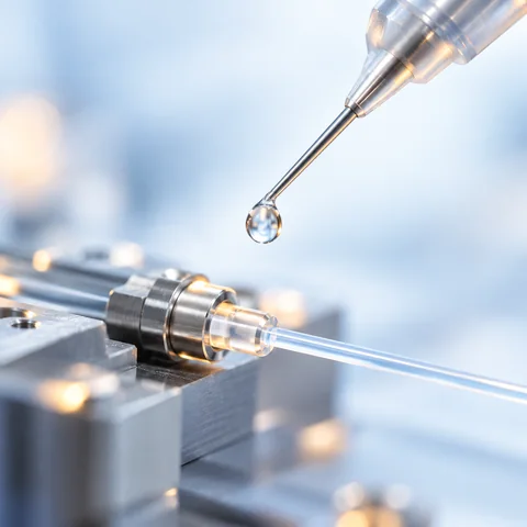
Define the optical alignment metric
State what will be measured, such as coupled power, insertion loss or component position, and define the reference point, instrument setup and permitted change.
Document the bond geometry
Record substrates, surface preparation, gap, fillet shape, dispense volume and adhesive location relative to the optical path and alignment features.
Control fixation and cure
Describe the fixture, UV access, irradiance or exposure method, thermal steps, shadowed regions and the timing of each measurement during the complete cure sequence.
Separate immediate and delayed movement
Measure during initial fixation, after full cure and after a defined stabilization period so short-term movement is not confused with later thermal or viscoelastic effects.
Validate reliability on the assembly
Repeat the alignment measurement after application-relevant temperature, humidity and mechanical exposures using the same reference and acceptance method.
INFORMATION CHECKLIST
Prepare these details for a productive material discussion.
- Optical alignment metric and instrument
- Substrates and bond-line geometry
- Dispense volume and fixture strategy
- UV and thermal cure sequence
- Post-cure and reliability measurements
TECHNICAL FAQ
Questions to clarify before evaluation
Does a bulk shrinkage value predict optical alignment change?
Not by itself. Assembly geometry, substrates, adhesive placement, fixture constraints and cure sequence all affect movement.
When should alignment be measured?
Measure at a defined baseline, during or immediately after fixation, after complete cure and after any required stabilization or reliability exposure.
Why should the finished assembly be tested?
The practical result is the optical and mechanical stability of the complete bonded structure, not one isolated bulk-material property.